As a Volunteer Firefighter and EMT, I am called upon to respond to emergencies.
In New York, volunteers are permitted to use warning lights while responding to these emergencies.
The lights are only a courtesy, and other drivers do not have to yield the right-of-way.
There is a bill in the New York State Senate to designate blue and green (volunteer ambulance) lights as emergency lights.
This would force people to yield the right-of-way and let us respond to emergencies in a quicker fashion.
It would not, however, permit us to disregard traffic laws.
Ok, I'm starting to wander now.
Anyway, In my last car, a 1995 Dodge Intrepid ES, I had strobes installed in the front grill (blue) and on the back parcel deck (amber).
They were excellent in warning other drivers, and most drivers were courteous and allowed me to pass.
When I traded in the Dodge, I removed all of the strobe equipment thinking I would install it in the GTP.
Unfortunately, the front strobes didn't fit, and I didn't want the rear strobes cutting down the already small rearward visibilty.
So I decided to install a completely new system, and sell the old one.
My goal with the GTP is to keep it as stealth as possible.
Nothing overtly "extra".
I decided on using Whelen products.
The "Hide-A-Way" system is wonderful.
If you have ever seen the Nascar Pacecar, you've seen the "Hide-A-Way" strobes in action!
They are hidden in the headlights and foglights.
For the Pacecar, Whelen also did some custom work integrating strobes into the mirrors, back window, and under the spoiler.
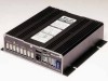
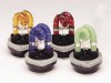
Here is what the Power Supply and Hide-A-Way strobe heads look like before the installation.
|
[ 32K ]
|
|
[ 35K ]
|
|
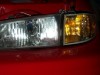
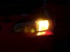
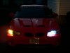
In my car, I decide to place a strobe in each headlight, each front turn signal, and each back-up light.
Eventually I'll add two more to the rear taillights, but not until I'm able to run red lights (have to be Chief or Assistant Chief).
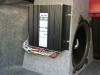
The power supply for these strobes will be mounted to the subwoofer box.
It is capable of running 2 sets of 4 strobes, with 4 different flash patterns on each set.
The total power output is 180w, which equates to 22.5w per strobe.
|
[ 49K ] | [163K ]
|
|
[ 37K ] | [127K ]
|
|
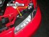
My biggest dilemma was running the strobe cables from the front of the car to the trunk.
I did this by running the cable inside the rocker panel.
Just behind the driver's side seat, there is an opening in the rocker panel that (after a lot of work) I was able to feed the 4 wire bunch through.
It was a close fit but works perfectly.
|
[ 46K ] | [152K ]
|
[ 45K ] | [145K ]
|
[ 55K ] | [193K ]
|
|
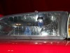
Placement of the strobe heads in the lights was easy....as close as possible to the focal point.
The difficult part was creating a perfect 1" circular hole.
I found that the best way was to (obviously) disconnect the unit from the car and remove all the bulbs.
Then I sprayed a 8:1 mixture of Jet-Dry (dishwasher additive) and water into the assembly, being sure to cover everything.
Using a 1" stencil I carefully cut the hole using a Dremel tool and a straight tungsten carbide cutting bit (#9901).
That made quick work of the job.
|
[ 39K ] | [115K ]
|
|
[ 36K ] | [143K ]
|
|
Once that was done I used more Jet-Dry mix and then fresh, HOT water to thoroughly rinse the shavings out.
There were still large droplets of water in the assembly and I didn't want them drying inside.
So I placed the whole assembly in a pillowcase, with the drainage point down, and swung it very fast in a circle for a few minutes.
The centrifugal force pushed the large droplets out and left only tiny ones.
Then I used a hairdryer to evaporate the remaining water.
The rest was quick!
Pop the bulb in and secure it with the supplied screws!
|
[ 31K ] | [106K ]
|
|
[ 33K ]k | [112K ]
|
|
Once all the wiring for the strobe heads was done, I needed to rig up a way of controlling the light heads.
At first I made a cheesy box that fit in the center compartment. It was ugly as sin, and didn't give me control over which heads were firing, but it allowed me to turn everything on and off and control the patterns.
Good enough for day-to-day use.
In the meantime I drew up a wiring schematic and started fabricating the new switch panels.
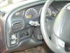
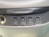
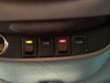
The primary panel (master on/off and pattern control) would be located in the cubby to the left of the steering wheel.
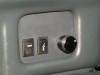
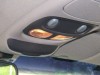
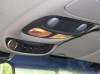
The secondary panel (individual head control) would be in the overhead cubby.
|

[ 22K ] | [ 77K ]
|
[ 36K ] | [131K ]
|
[ 23K ] | [ 80K ]
|
|
The primary panel has two rocker switches and a rotary switch.
The left switch controls power to the entire system and is only active if the car is "On".
That supplies power to the middle 3-way switch.
In the "Up" position, this switch turns all the heads on.
The "Middle" position is "Off".
And the "Down" position defers control to the secondary panel (overhead).
The rotary switch allows me to select one of 16 different flash patterns.
|

[ 17K ] | [[an error occurred while processing this directive] ]
|
[ 15K ] | [[an error occurred while processing this directive] ]
|
[ 20K ] | [[an error occurred while processing this directive] ]
|
|
The secondary panel has four rocker switches.
It's current configuration is Front, Front, Rear, Rear.
The nice thing about using this cubby is that the cover can be shut to conceal the switches.
I am VERY happy with the end result! :)
If you have any questions, feel free to E-Mail me.
|